| PROBLEM | SOLUTION |
|---|---|
| LC Driver Problems: The computer is unable to communicate with the controller. Error says error communicating with controller axis 1. Check scale factors in setup and make sure all cables are connected. | First, identify whichController box you are using (LC / LP Control box or LC Plus) Windows 98, 2000, XP: Click Start in the lower left corner of the screen Click Settings Click Control Panel Double Click System Click the Hardware Tab at the top Click Device Manager Alternately, for a shortcut, press and hold the windows key on the keyboard and tap the pause-break button (typically in the upper right) Windows Vista, 7: Click Start in the lower left corner of the screen Type "Device manager" (without the quotes) in the text box and press enter Once you are in the device manager, you will see one of a few scenarios: If you see "System DMA Controller" with a yellow question mark next to it. Click here to see photos |
| All axes are frozen. All Axes will not move via interface or when running an NC file. Receives multiple "M-x Position error, no power to controller. Re-enable controller?", circular error | Possible causes: 1) It is possible the router's controller is simply not powered up. 2) The SCSI cable, for some reason, is not making the required connection between the PC to the controller. 3) The Computer card is either not functioning or not properly installed 4) The Controller mainboard is not functioning. Solution: 1) Turn the router's Controller "ON", and verify that ALL the controller's LED lights are "Lit" and the controller is "ON" 2) Clean and re-seat the SCSI connector, starting with the end connecting to the PC. Test the cable for continuity with a multimeter. 3) Check Device Manager and verify PCI card is working. If not, reinstall driver and/or re-seat the card in the PCI slot. XP: Right-click "My Computer", click "Properties", click "Hardware" tab, click "Device Manager" button. Vista and Windows 7: Click "Start Button", click "Control Panel", click "Device Manager" 4) If you suspect the controller mainboard is not functioning properly, contact Techno's Technical Support department. |
| Tighten Axes | In rare circumstances, one of the axes may suffer from tightness in only certain spots. To find this tightness, there is an axis lag test that can be run. This test is available in 1.421.10 and higher. Move the machine to an inch or so before the problem spot. Click Help Click Machine test, then read and understand the warning. You will be presented with the machine test screen, as follows:(Your version may have the buttons named "Run--v", but the function is the same. Click here to see photo. Enter a distance (negative or positive) in the text box below the axis you wish to test. Set the G IPM to a low number, like 20. This is the speed at which it will test. Click the Run [xyza] lag button (or the run--v button) The axis will creep along slowly, showing the servo lag. The results may be difficult to interpret. When in doubt, shift-click the image to save a screen capture of it to c:\mechanics.jpg and email techno the file. You are looking not for high amounts of lag, but lag that increases or decreases in magnitude (spikes or slants). |
| Controller Not Enabled. You keep getting a message saying controller not enabled. Check power, e-stop or cables. | Ensure the Emergency Stop Switches are disengaged by pressing them in and then rotating them out. Then try to enable the controller again. If the problem persists: If your control box has a ready light, while watching the ready light, click to enable the controller. The exact moment you click to enable, the ready light may blink. You may need an assistant to click to enable while you watch the ready light. Note that your control LED badge may be blue and labeled with different text. The ready light is the only important LED for this test. If the ready light blinks one time like this (this video cycles every 10 seconds, be patient): Click here for photo The problem is the E-stop loop. Note that the E-stop loop runs through not only the emergency stop switch, but all of the motors as well. This is done to prevent a dangerous situation. |
| Axis will not move via interface and cannot be moved manually. Receives "M-x Position error, no power to controller. Re-enable controller?", error Can jog other axes Customer is probably cutting wood or another material where a lot of debris is generated. The ball nut is possibly jammed-up with debris. This is especially likely if the machine is used to cut wood or other material that easily becomes airborne after being cut. | Obtain a can of WD-40 that still has the red straw. Hit "E-Stop" and POWER DOWN machine Lock out power Thread the red straw from WD-40 can into groove of ball screw and into the ball nut and blow it out with copious amounts of WD-40. This will be messy, avoid being underneath the nut during this process. Take all necessary precautions to prevent eye and lung exposure to oils. After putting a lot of WD-40 into the ball nut, attempt to spin it by hand, being careful around the belt and pulley. This will force the debris out of the nut. Once the machine is moving again remove all the WD-40 with a rag and lubricate the machine. DO NOT leave the WD-40 residue on the ball screw. Also note that over lubricating the machine in a dusty environment frequently leads to this problem, as the dust gets stuck to the excessive debris. |
| Estop is broken. Estop light is blinking red. Estop problems. The ready light is not blinking while attempting to enable the controller. Controller box Your machine is using the LC Plus controller or a Premium Class controller. It is NOT a low power LC or LP controller. You receive one of the two following error boxes: Controller not enabled. | Power down the machine and computer and Lock out power. Ensure the cable that goes between the computer and the control box is secure on both ends. Verify control cable. Unlock power, power back up and test again. If this is a new install or a new computer that has not yet worked properly, Verify the drivers for the system, as if they are not installed on an LC plus or Premium controller, this is a symptom. Power down the machine and computer and Lock out power. Disconnect the cable (from the PC first) and inspect the pins in the connector, then inspect the connector on the Control Board side. The PC Connector is more likely to have issues since it is more frequently removed and replaced by the user. Bent pins can be subtle and difficult to see. Inspect the cables very carefully. A pin does not need to be completely destroyed to cause a problem. Even slightly tilted pins can contact other pins when placed into the connector. If you are unsure about the integrity of the connector pins, carefully take a clear picture and email it to tech support. |
| Lock out power | Locking out power: Locking out power prevents the machine from harming the user while the machine is being worked on. Dangerous voltages and the potential for the machine to move will exist if the machine is powered up while it is being serviced. NEVER WORK ON OR INSIDE A MACHINE THAT IS POWERED UP OR HAS THE POTENTIAL TO BE ACCIDENTALLY POWERED UP The regulations at your workplace may vary from standard regulatory requirements. When conflicting regulations are encountered, follow your workplace regulations. If there is ANY uncertainty, contact your workplace supervisor. Locking power out from a machine is required for any servicing. Power down the machine and the computer by the normal methods. Remove the power source from the machine and lock it out as per your workplace regulations. This may involve an actual lock on a breaker box, a nametag, or some similar methods. Many machines have multiple sources of power (control box, spindle, etc). Be sure to find all power sources and lock all of them out prior to any service. |
| Position Error. Scenario: You are repeatedly getting the following message box: M! position error (y axis) no controller power. Re-enable the controller? Problem: The machine is unable to travel to the position that has been requested of it. Solution: There are a few pieces of information necessary to determine the cause of this issue. | • Does the machine move properly in any of the axes? If the machine does not move in any of the axes, you should Verify power to the machine • Does the machine Run away before getting the position error? • Verify power to the machine • Ensure feedback in setup • Are you attempting to move the system at a speed higher than possible for the Controller box? • Is the machine smashing into the End of travel? • Is there a blockage in the axis that is causing a Frozen axis? • Check for Amplifier status. • If the symptom of the position error is that it only occurrs in a specific location on the machine, you can test for Axis tightness. This is very uncommon. |
| Run away error. When attempting to move an axis by jogging or when running a file, one axis "takes off", usually resulting in a crash at the end of travel or a red box position error Ensure feedback in setup When axis is pushed by hand, the numbers in the Positional Display for that axis do not reflect the change in position. When the Motor cable swap procedure is performed, the same axis exhibits this problem. The encoder feedback data is not reaching the controller. | The most common cause is a damaged encoder. Contact tech support to discuss having the encoder replaced. Sometimes cables can be damaged and cause this problem. The potential cables for this problem are the cable between the PC and the Controller box, and the rectangular cable between the motor and the Controller box. |
| LC Drift issues. | Click here |
| Dusty pause error. The Pause button on the Start Stop Box is dusty or damaged. Symptoms include constant pausing, and home being cancelled due to pause button (in newer versions of the software). The following style Start Stop Box and a similar box that looks identical except for a lack of Emergency-stop switch has buttons that can become unusable due to dust buildup. | This model Start Stop Box has been discontinued. To repair the problem, Contact Support and obtain a new button or a new style Start Stop Box. In a pinch, the buttons can be made to work temporarily by one of the following methods: Repeatedly exercise the switch aggressively. Disassemble the switch and clean the contacts Replace the switch with any other similar switch (pause is normally closed and start is normally open) Another option is to disable the Start Stop Box in software. The emergency stop button will still work. To disable the Start Stop Box, click Setup, Advanced, Touchpad and Remote. Change the Start Stop Box mode to 0. |
| Encoder damage. | Encoders are sensors hooked up directly to servo motors. They monitor the position of the motor so the machine can position accurately. If there is damage to the encoder, it will misbehave in a number of different ways. The motor might run away (typical of a destroyed encoder) The position might drift (typical of a dusty encoder) The system might generate position errors It is normally required to have motors with encoder problems serviced by Techno CNC. It is not recommended that end users repair or replace encoders, which are very delicate and require experience to install. |
| Home switch repeatability error. If you receive a message that says The index pulse is within the home switch repeatability. Either disable index pulse homing or rotate the pulse relative to the switch. | This means there is an issue with the distance between the index pulse and the home switch. Your message will be similar, with numbers and axes labels changed. You may read more on Index pulses here. This link is not critical to fixing this problem. To solve this problem: Lock out power from the machine Disconnect the connection between the motor and the ball screw (Remove the belt or Disconnect the shaft coupling). Spin the motor 1/2 turn and reconnect the motor to the ball screw (Belt or shaft Coupling). This will increase the distance between the limit switch and the first found index pulse, eliminating the error. Critical Note: * Performing this procedure will shift the home position, resulting in the NEED to re learn Tool stand locations and any Stored Offsets. |
| Jogging the wrong way. When the router jogs in the wrong direction, the cause is most often an incorrect sign in the Scale factors. When jogging, the machine moves in the wrong direction. There is a setup issue. The scale factor settings in the Techno CNC Interface need to be adjusted. | Click on Setup > System Find the “Mx Scale” section. Change the sign of the axis affected. If it has a ‘minus’ sign, remove it. If it has no sign, add a ‘-‘ before the number. Click “OK” to save change In versions prior to 1.423.4, Soft limits could occasionally cause this behavior. If this problem happens only occasionally, changing the scale factors may not be the appropriate answer. If soft limits are in use, either discontinue their use or upgrade the software to the latest build, which has a fix for this soft limits bug. |
| Test for backlash. | Click here |
| Computer speed issue. You are experiencing stuttering (either visible or audible) while cutting (jogging the machine works smoothly), or you see the following error message after a run: Therer were 5625 computer speed issues with running that file. Contact support. The computer running the machine is either under powered or too busy doing other tasks to keep up with running the machine. | If you are not receiving the error message but you are seeing or hearing stuttering, there is a test to perform to verify the problem. Obtain software version 1.422.1 or greater if you do not already have it. Documentation on upgrading the software for test purposes Click Setup Click Advanced Click Software Switches Check the box marked “Warn” next to “Interface update frequency”. Run another file (it is okay to run a file “In the air“, a speed issue will happen regardless of the lack of material. After the run, you may receive the error box shown above. If you do receive this error, follow the instructions below. If you do not receive this error, the problem is possibly loose mechanics, or issues with gcode files. If you are receiving this error message or if you have an old version of the software and suspect this is the problem: This message means the PC is unable to keep up with the other tasks it is being asked to do while running the machine. These tasks might involve legitimate work (network access for files, virus scanning, general computer background things) or viruses and malware. Start by closing unnecessary programs while cutting on the machine. On older computers, it may be necssary to Disable the network. Most modern multi-core computers can run the CNC interface and a network connection simultaneously, but this is not always the case. Wifi cards are especially prone to hogging CPU resources. Inspect the computer for viruses and malware. Note that even very old computers can run the Techno interface, but even new computers can get bogged down with unnecessary/problematic software that prevents smooth operation. If the problem persists past cleaning the computer and disabling the network, change the drop down box “Interface update frequency” (located near the warn button in setup -> advanced -> software switches) to “Never”. If the problem continues, try running with a different PC if possible. |
| Cuts are drifting in one or more axes. Depending on the version of the software, and the tasks being done, an error message may be received indicating loss of pulses or axis drift. | Problem There are a few common causes for this problem: Loose pulley or mechanics Electrical interference/noise Problem with NC file geometry LC+/MP/Premium controllers only: Verify control cable Solution There are a few pieces of information necessary to determine the cause of this issue. Does the drift continue in one direction, or does it bounce back and forth for a short distance? After the drift happens, is the origin of the part exactly where it was before the problem occurred? First: Test for encoder pulse issues Next: Test for mechanical drift issues |
| Jog button missing. The arrows for the jog buttons are missing after a new installation. The icons for jogging are blank. | The computer must be rebooted after installing the software. This will load the proper arrows. If the problem persists, contact tech support Or click Setup ->Advanced ->Software Switches and check the box “Use Basic Font” |
| Axis drifted. You get the error message that says: WARNING: Axis 1 drifted by approximately: -.2094. | The error code associated with this message is: 27102010 This error means the machine found the home switch in a much different location than it has previously. This suggests that something in the system is loose. Possible loose components for this problem are, in order of probability: Pulley on ball screw shaft Pulley on motor shaft (if it is a low power or otherwise unkeyed motor shaft) Loose home switch or home switch bracket Loose ball screw bearings Loose ball nut How to check directly for loose pulleys If this error is preceded by the following error message:Click for photo The problem is NOT loose mechanics, and you should follow the following route: Axis lost pulses error message Note that this error will only come up if the index pulse is enabled on that axis. Still not sure what is going on here? Read: About drift issues |
| Pausing while running. The machine pauses repeatedly and constantly while running a file. The issue is that the machine was told to pause the file. | There are a few reasons the machine might constantly pause while running a file. The start stop box might be in the wrong mode The pause switch may be dusty or damaged Keys may be pressed or damaged on the keyboard. Check the keyboard by cleaning it or replacing it with a similar model. Do not attempt to do other things on the computer while it is running a file. In order to run a file, the Techno CNC interface must be in complete control of the computer. The user is unable to do part design, CAM work, web browsing, etc, while a file is running. Performing any of these tasks will pause the run. |
| Index pulses. | The index pulse is a very useful aspect of the machine. Primarily, the index pulse is used to aid machine home. The index pulse is one unique line on the encoder. It occurs one time in the entire revolution. It is a very special pulse indeed. To turn on the index pulse functionality of a Techno Router: Click Setup Click advanced Click Homing params Check the box for Index next to all the axes. Read the warning and take it into account. Note: Enabling the index pulse on the machine will slightly change the location of home on the machine. If you have a toolchanger or fixtures on the machine that are referenced with offsets, these spots will need to be re-learned. When homing without the employ of the index pulse: The machine will home towards the end of travel until it finds the limit switch. After tripping the switch, it will back off until the switch is no longer actuated. After the switch is released, the machine home has been found. Due to the nature of limit switches, differences in approach speed, ambient temperature and age will * result in imprecision of the switch to the tune of anywhere from 0.0005″ to 0.002″. For most applications, this level of imprecision is acceptable. When this is too much imprecision, the index pulse is employed. When the index pulse is being used: After backing off the limit switch until it disengages, the machine continues to move away from the switch until the index pulse is observed on the encoder. This pulse location is defined as the home. Now the system has homed to the resolution of the encoder/mechanics instead of the home switch. A problem can exist wherein the index pulse is found very close to the home switch location (or one full turn away from the home switch). This results in a Home switch repeatability error. |
| You get a message that says M1 position error YAXIS NO CONTROLLER POWER. Problem: The machine is unable to travel to the position that has been requested of it. | There are a few pieces of information necessary to determine the cause of this issue. • Does the machine move properly in any of the axes? If the machine does not move in any of the axes, you should Verify power to the machine • Does the machine Run away before getting the position error? • Verify power to the machine • Ensure feedback in setup • Are you attempting to move the system at a speed higher than possible for the Controller box? • Is the machine smashing into the End of travel? • Is there a blockage in the axis that is causing a Frozen axis? • Check for Amplifier status. • If the symptom of the position error is that it only occurrs in a specific location on the machine, you can test for Axis tightness. This is very uncommon. |
| Changing the home direction | The Techno interface specifies which direction the machine travels in when homing. CRITICAL NOTE: After changing the home direction for an axis, any Stored Offsets and Tool Stand Locations will need to be re-learned. If the home direction is to be changed due to preference or because an axis is traveling in the wrong direction during home: Click Setup Click Advanced Click Homing Params You will receive a screen as such: 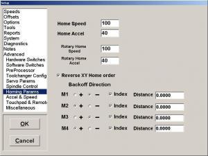 The options buttons next to + and - dictate the direction of home. To change direction, simply choose the button opposite of the one currently selected. Typically, M1 is the Y axis, M2 is X, and M3 is Z. The motors are labeled from the ground up, M1 being the physically lowest motor. |
| Machine hits the end of travel while running. Set the origin | Set the origin Setting the origin For proper operation, the machine has to "match" up the coordinate system with that of the drawing that it is running. The origins are sometimes referred to the zeroes. Do not confuse this position with the home, which is the end of travel of all of the axes. The origin of the material is typically at one of the corners of the part. Sometimes it is in the middle of the part. Common to cabinet making and some other woodworking applications where stock isn't flat and veneers are involved, the Z zero is at the bottom of the material. The origin of the part in the CAM software relative to the material must match the origin of the machine relative to the material in the real world. If these origins do not match, the part will not be cut properly. To set an origin, jog the machine to where the origin is and click Zero on the interface and then All. To quickly set the origin for the Z axis only, use the touchpad by placing the touchpad on the surface that is to be Z zero, hovering above the pad, and clicking Tool, then Touch off Z zero. Note that this will not set the X and Y zero. To adjust the origins by a set amount without moving, double-click the origin readout in the upper right of the interface and enter values by which to move the origin around. This is especially useful for moving the origin to a spot that is not physically achievable. |
| Machine cuts too deep or not deep enough. The machine is cutting too far into a part or not far enough. This is an issue from the start of the file and stays at a consistent depth through the run (it doesn't increase or decrease in depth over time, which is a different problem) | This is typically one of the following possibilities: The origin of the part is not set properly. The Scale factors are not correct |
| Cuts are drifting in one or more axes. Depending on the version of the software, and the tasks being done, an error message may be received indicating loss of pulses or axis drift. Problem There are a few common causes for this problem: Loose pulley or mechanics Electrical interference/noise Problem with NC file geometry LC+/MP/Premium controllers only: Verify control cable | There are a few pieces of information necessary to determine the cause of this issue. Does the drift continue in one direction, or does it bounce back and forth for a short distance? After the drift happens, is the origin of the part exactly where it was before the problem occurred? First: Test for encoder pulse issues Next: Test for mechanical drift issues |
| Home stops immediately after starting the home procedure. You may or may not receive a message "Home cancelled due to..." (pause, keyboard, etc). This message only happens in version 1.422.1 and newer. | If the message indicated that home was stopped due to pause, the issue is likely with the start stop box: The start stop box might be in the wrong mode The pause switch may be dusty or damaged If the message indicated that home was stopped due to the keyboard, check for problems with the keyboard, such as things leaning on it, dirty/damaged switches, etc. If there was no message, the same issues as above may be the case, however, it will take more effort to track them down. Check for a Dusty pause button Check the keyboard by cleaning it or replacing it with a similar model. |
| The machine pauses repeatedly and constantly while running a file Problem: The issue is that the machine was told to pause the file. | There are a few reasons the machine might constantly pause while running a file. The start stop box might be in the wrong mode The pause switch may be dusty or damaged Keys may be pressed or damaged on the keyboard. Check the keyboard by cleaning it or replacing it with a similar model. Do not attempt to do other things on the computer while it is running a file. In order to run a file, the Techno CNC interface must be in complete control of the computer. The user is unable to do part design, CAM work, web browsing, etc, while a file is running. Performing any of these tasks will pause the run. |
| The Pause button on the Start Stop Box is dusty or damaged. Symptoms include constant pausing, and home being cancelled due to pause button (in newer versions of the software). | This model Start Stop Box has been discontinued. To repair the problem, Contact Support and obtain a new button or a new style Start Stop Box. In a pinch, the buttons can be made to work temporarily by one of the following methods: Repeatedly exercise the switch aggressively. Disassemble the switch and clean the contacts Replace the switch with any other similar switch (pause is normally closed and start is normally open) Another option is to disable the Start Stop Box in software. The emergency stop button will still work. To disable the Start Stop Box, click Setup, Advanced, Touchpad and Remote. Change the Start Stop Box mode to 0. |
| You receive an error indicating that the start button is being pressed on startup OR The Start and Pause buttons on your start stop box are not working properly, but in diagnostics, they behave properly. | Click Setup Click Advanced Click Touchpad and Remote Click the button for "Test Remote" You will be prompted to press the start, then the pause buttons. This will set your start stop box mode properly. On most common machines, the proper mode number is 1 or 5. If your start stop box continues to work improperly, ensure proper start stop box operation by going through the procedure in the SSB Diagnostics page. |
| OCF Error (on the controller) | Cut power to the inverter and restart it. |
| Axis 1 lost pulses! Index pulse found | The error code associated with this problem is: 04052010. This is a very critical error that can result in a lot of problems: Machine drift Runaway conditions Location problems Cut quality issues The causes of this problem are (in order of probability): Broken encoder / Dust on the encoder (if the environment is dusty) Bent Control Cable pin or damaged cable (LC Plus or Premium electronics only, this is NEVER caused by a bent pin on an LC / LP controller) Nicked or damaged encoder cable wire |
| error below: please contact techno and be ready to provide the following code over the phone: 0077972 | Contact Techno and be prepared to provide the number given in the code (in that image, the number is 0077972. This message will occur when a new PC is installed or on a new machine. Once the proper code is received, the message will not show up again. There are several days and thousands of runs of grace use before the machine requires the code. This is to avoid a shutdown over the weekends or holidays. Be sure to obtain the code as soon as possible when the message is received. |
| Circle error of 0.0890. Circle error in preview. | This error indicates that the gcode used to make the arc is improper. There are two issues when dealing with this error. The error may be very small and unavoidable. In most situations, there will be "Round off" error when creating arcs. If the first line, "Circle error" is smaller than .001", it can be ignored, and the tolerance for errors should be increased. To increase the previewer circle tolerance error, click Settings in the lower right of the previewer, and increase the circle tolerance to 0.001 or 0.002. If the error is higher than that, the gcode is being output incorrectly. There is probably a problem with the POST in the cam software you are using. Email the offending file to tech support, and include a message that states what CAM software and CNC interface versions you are using. |
| Machine doesn't work after PC upgrade. After upgrading the PC used for the machine, nothing seems to work. The Techno CNC Interface might open, but it does so with errors. | Check the main troubleshooting page for the error that most closely resembles the error you are receiving when starting the cnc interface. |
| Touch off problem. When moving to touch-off, the tool moves in the wrong direction (away from the touchpad), and it moves very slowly. Problem There is a connection issue. The software thinks the touchpad is already contacting the tool, but the sensor or cable connection is damaged or shorted. | The main cause of this problem is damaged wiring the connector at the touchpad. Only one wire (the red one) should be exposed to the connector for the touchpad. If you disconnect the touchpad connector on the control board side, you will see two pins in the connector. Test them with a multimeter set to continuity. They should NOT have continuity. If they do, there is either an exposed segment of the black wire in the connector at the touchpad or a break somewhere along the wire that is shorting the black wire to the red. Note that version 1.421 (and up) of the control software will warn you if this behavior is detected. The error message will read: "Touchpad is shorted to ground. Cancelling touchoff" This error either means the touchpad is indeed shorted, or the computer is looking for the touchpad in the wrong place (Riser card, 4th axis, LC+, options in Setup->advanced->Touchpad and remote - try testing with other options selected. A successful touchpad test is a good indicator of a working touchpad setup.) |
| The arrows for the jog buttons are missing after a new installation | The computer must be rebooted after installing the software. This will load the proper arrows. If the problem persists, contact tech support Or click Setup ->Advanced ->Software Switches and check the box "Use Basic Font" |
| When running a File, the Progress Bar or the Current Position is not being updated. There is a setup issue. The settings in the Techno CNC Interface need to be adjusted. | Visit Interface Update Frequency (below) to set your software appropriately. This setting will allow your software to update the positional and progress display much faster. Important Note The different computer speed options exist due to different performance among host computers. If you machine starts jerking or decreases cut quality, this means that the computer is not fast enough to process the cutting job and to update the screen. In this case, make sure to update the range to a less intensive setting. |
| Interface update frequency | This gives you the ability to control how often the software updates the position and progress bars when running a file. There is also a checkbox there labeled "warn" that will tell you if your machine isn't fast enough to run a file at the current setting. So for example, if you set the software to update often, after a file is run a popup message may say "There were 3944 computer speed issues when running this file". Note that small numbers (10) are no problem. Large numbers (5394) will result in obvious jerking, and you should turn down the updates to allow the PC to control the machine. Interface Update Frequency Servo Control Software version ≥ 1.422 Click on Setup > Advanced > Software Switches. The drop-down box labeled "Interface Update Frequency" allows you to select Never, Sometimes, and Always. 'Never' plays it safe and only updates during non-cutting operations. 'Sometimes' is the default behavior, and is consistent with how it worked in the past (updates only when the machine comes to a stop). 'Always', attempts to update the display every time it commands the machine to move (over 500 times a second). Fast, dual-core machines can handle the setting at 'Always', without a problem. See our computer requirements for details. Older versions Servo Control Software version 1.421 This feature use to be called "Computer Speed Assist". Open the Techno CNC Interface. Click on Setup > Advanced > Software Switches and find the "Computer Speed Assist" checkbox. Set the value that works best for your machine: Less than -11 updates progress bar and position numbers. Between -10 and 0, updates the progress bar and the position numbers only when there is a full stop in the move. Between 1 and 5, updates the progress bar only. Greater than 6, it does not update anymore. Click "OK" to save changes. |
| The toolchanging spindle hovers above the tool holder when picking up or returning the tool. | One of two issues is likely in play: There is inadequate air pressure to the toolchanger (this is likely if there is no tool currently in the chuck -- the spindle is going to do a pickup). Alternately, there is an issue with the tool sensors. First, ensure proper air pressure for the toolchanger. If the air pressure is adequate (90 psi or higher): Check the large ribbon cable that goes between the toolchanger control box and the controller. If the machine is a MP/LC+/Premium controller, the cable will plug into the PCI card or Riser card next to the PCI card. On fresh installs, this is a common problem. If the machine is an LC/LP controller, this cable will plug into the LC control board. This is typically not a problem on LC/LP controllers, as this cable is attached at the factory. If this cable is plugged in properly, the next step is to check the sensors for the toolchanger. |
| The cutter plunges too deep or not deep enough after changing tools. The system cuts properly for the first tool. The tool lengths are incorrect. | Test the tool lengths: Have the machine retrieve the first tool. Find a reference point on the machine that is stable (not a loose piece of material or something that will move). Move the spindle so the cutter is barely touching the point. Zero all three axis at this point (after this, the machine should read "0.000" in the upper right under all 3 axes). You may also use the touchpad to zero the Z axis to the top of the material, but don't forget to zero X and Y. Change tools to the next tool. Click Goto, and fill in 0 for X and Y. Leave the value in Z as it is. Click Go. Slowly jog the Z axis downwards until it is similarly touching the part as before. NOTE: It is important not to use Goto to move the Z axis down, as if there is a length error, this might result in damaging the material or the cutter. Once the tool is barely touching the material as before, compare the Z readout in the upper right. If the tool lengths are taught correctly, this number should be very close to zero. If the number is far off from zero, learn the tool lengths. Repeat this test procedure for all the tools on the machine, comparing one tool to all the subsequent tools. If all the tools are learned properly and the file still cuts deeper or shallower on subsequent cuts, the issue may be one of axis drift. |
| While preprocessing a file, the computer freezes every time (the issue is not solved by a reboot and another attempt at preprocessing) Frequently, the system freezes at or around 50% preprocess. If left for a very long time, it might increase a few percentage points. | Cause: The system is preprocessing the files at a very low cut speed. The amount of time a file takes to preprocess is proportional to the amount of time the file will take to run. Feed speeds less than 1 unit per minute typically result in this behavior. Solution: Check to see if the feeds and speeds are set to override. This is in the first menu of setup, under preprogrammed or override speeds. If the speeds are set to override, the values for the overridden speeds are likely too low. If the system is set to programmed speeds, it is likely that the speeds set in the file by your CAM software are too low. Edit the file and look for F commands followed by a number - this is the speed. It is common for CAM software that has not been set up properly to output a speed of F0.1 . Either override the speeds or re-post the file with a reasonable speed. |
| when running a file, monitor goes black. But it does not malfunction if knife switch is not giving power to spindle. Blank monitor. | There is likely a problem with the monitor and the level of noise coming from the spindle. Use a new or different monitor. |